# Best Practices in 3D Graphics
General practices for successful and problem free model handling within 3D software
---
### Quick Checklist
This is a simplified checklist for submitting 3D models to Simlab software
##### Scene/File Setup
● **System and Display Units** should be set to **Centimeters**; model is **real-world scale**
● All Geometry is under one group (*No object linking*), and one Layer is named after the scene
● **No Cameras, Lights**, or anything other than the model’s geometry and materials, should be in the scene
● All nodes for objects, groups, layers, and materials are **uniquely named** (*no duplicate naming*)
● All textures should be placed in their own folder titled ‘Textures’ (*or saved into the model file itself **GLB/GLTF***)
● All textures should have **Relative Paths**
##### Geometry
● No Isolated Vertices, Overlapping Vertices, or Overlapping Faces
● Xforms, Transform, and Scale are reset, and the model’s overall xform should have its center pivot
centered on the origin of the XY Plane and touch the lowest Z point
● No visible faceting, texture stretching, visible seams, or flipped normals; all objects must contain at least one smoothing group
● All modifiers besides must be collapsed
● **UVs** should be **Non-overlapping** and logically **unwrapped** to Maximize Texel Density
##### Textures
● Textures are **8-Bit**, **RGB**, and in **JPG** or **PNG** format
● Textures are square resolution and same resolution is used within a given texture set
● All Base maps are included for DCC and RT (*if applicable*)
● Textures follow naming conventions and are plugged into correct slots
● Texture map contribution is set to 100%
● Texture Gamma for all maps is set correctly (*Automatic or Override 1.0*)
##### Materials
● All Geometry has a material applied of the correct type
● Materials do not contain any maps or procedural nodes that are not listed in this document
● Normal Bump node must be used for all Normal Maps
● If Refraction is used, all settings should be correctly configured
Preparing 3D models is a complicated task, if you do not have prior experience doing so, we recommend using premade models from 3D shops and/or the services of a professional 3D artist
---
---
### Advanced instructions
We recommend following the [**stem cell modeling requirements article from the 3D website Turbosquid.**](https://resources.turbosquid.com/stemcell/stemcell-3d-modeling-specification/)
##### File format
It is best to share with us models in file formats requested by **specific software.**
**SIM-ON**: GLB, GLTF
**STAGES**: OBJ, FBX
##### Avoid Bad Geometry
● No isolated vertices - inefficient, can cause issues
● No coincident vertices - cannot run smoothing operations, may pull apart
● No coincident/coplanar faces - leads to z-fighting in real-time
● No coincident edges (unwelded seams)
● No inverted face normals
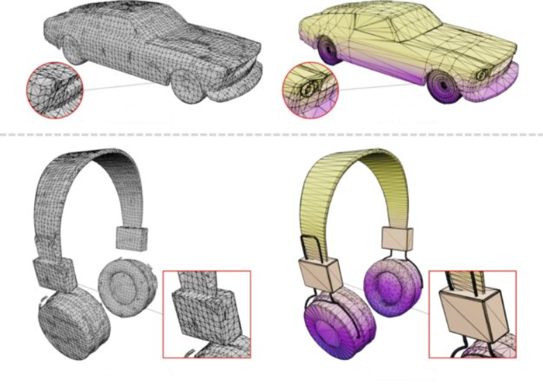
##### Sensible Polygon Detail
We would prefer the models to have as few polygons as possible without sacrificing
important details as well as ensuring clean/non-faceted silhouettes. This is a hard judgment call.
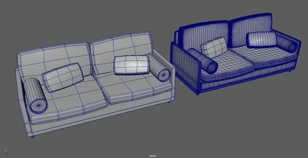
##### Maximum Size
The maximum size of the geometry for real-time purposes should be less than 100K vertices.
Smaller is better, but one has to be realistic.
---
### Transforms
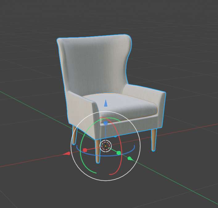
##### Scale
All objects should be created such that they are in real-world scale. This allows for multiple objects to be imported into the same context without scaling issues. It also improves the ease of accurate lighting because it enables lighting based on physical quantities.
##### Position
Objects should be placed such that its natural base is located at 0,0,0.
##### Orientation
The object should be oriented so that its natural front is on the **Y axis**, facing to the positive side of the axis.
---
### Scene
##### Hierarchy
We allow for an internal object hierarchy. It is best if it is logically grouped.
Nodes should be in English and have meaningful names. Calling things Box001, Box002,
Plane003 is not the best way.
##### Node Limits
One should aim to only have a sufficient number of nodes but not an excessive
amount. 5 to 40 nodes per model.
#### UVs
All objects should have UV sets that are natural. We recommend one or two UV sets.
##### Primary
The first UV set is used by the albedo map, normal map, bump map, roughness map,
metalness map, anisotropy map, and emissive map. If you want to have different map
repeats you can set the individual texture map tiling and offset values.
##### Unwrapped / Baked
The second UV set, if it exists, is generally unwrapped. It is used by the quantities
that are baked onto the mesh, such as the light map and the ambient occlusion map.
##### Normals
Each object should have normals specified as either a normal set or smoothing
groups. Creases can be specified via smoothing groups, very disconnected normal sets, or
via edge crease values.
---
### Textures
##### Power of 2
Use texture in power of 2, such as 4096x1024, 1024x1024, 1024x512 or 128x512.
To avoid loss of quality by rescaling of textures, it is best to create your textures in a power of 2 size.
##### Formats
We recommend JPG and PNG texture formats. PNG should only be used for
textures that require an alpha channel as it does not compress as well as JPG.
##### Maximum Sizes
Real-time applications require texture sizes to be less than 2MB in total per model
unless the model is uniquely complex.
##### No Procedurals
Procedural textures cannot be correctly transferred between tools, thus we would
prefer these to not be used.
##### Naming Conventions
Texture maps must be named with the same name as the material they are applied to
followed by the correct suffix. All texture file names must be suffixed correctly as listed
below. There must be no text after the suffixes.
Example: GlossyPlastic\_Diffuse.PNG.
Some additional maps may be required when additional effects are present (Self
Illumination, Opacity, etc.). Follow suffix naming conventions listed below.
---
### Materials
##### Unpacked Logically Separate
Materials should be one actual physical material per material definition. Thus if there
is plastic and also a metal mesh in your scene these should be represented by two separate
material definitions rather than a single material definition with packed textures. We can
pack textures ourselves if we so choose.
##### Color or 100% Maps Per Property
It is best to either use a color or a 100% map per material property rather than using
a combination. The reason that combinations are problematic is that many tools do not
interpret the combinations of color and map in the same fashion. Texture map contribution is set to 100%
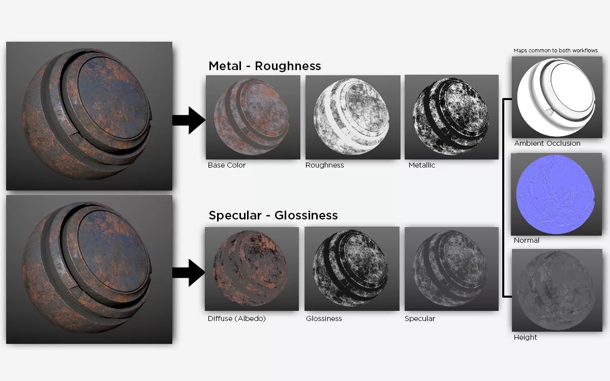
#### Parameters
Like many modern tools, we support the standard physically based model.
In particular we recommend using the following parameters:
**Albedo** Also called base. Uses the primary UV set. The surface color. sRGB space.
**Roughness** Uses the primary UV set. Surface roughness, controls both diffuse and specular
response. Linear space.
**Metalness** Also called Metallic. Uses the primary UV set. The metallic-ness (0 = dielectric, 1 =
metallic). This is a linear blend between two different models. The metallic model has no
diffuse component and also has a tinted incident specular, equal to the base color. Linear Space.
**Normal** Uses the primary UV set. Perturbs the surface normal. Uses the standard normal
map tangent space. Linear space.
**Bump**
Uses the primary UV set. Perturbs the surface normals in a low quality fashion. Linear space.
**Emissive**
Uses the primary UV set. Light emitted from the object surface. Specified in Lux. sRGB space.
**Opacity**
Uses the primary UV set. The opacity of the object, how much can one see what is
behind the object. This means that it affects all aspects of the object’s interaction with light. sRGB space.
**Displacement**
Uses the primary UV set. This is a vector quantity that displaces in 3D the surface
vertices. Linear space.
**Unwrapped**
These are the unwrapped quantities that are also usually baked.
**Light**
Uses the unwrapped baked UV set. A baked light that is used as indirect diffuse on
the surface. Thus it has the effect of lighting the albedo diffuse layer. sRGB space.
**Ambient Occlusion**
Uses the unwrapped baked UV set. A measure of the accessibility of a point on a
surface to the environment surrounding an object. So it modulates the contribution of for
example a light probe or sky dome. It doesn't model shadowing though, so it shouldn't be
applied versus lights that are not completely surrounding the object. Linear space.